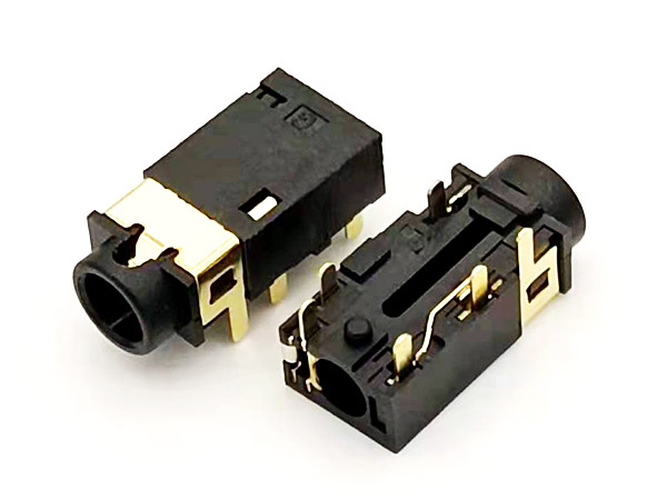
Dimensions
How to mark the dimension and how much the tolerance value is appropriate is not the decision of the designer or the person who marks the dimension, but the product requirements (function, process requirements, process capability). Key dimensions for finished products are generally important dimensions usually used by customers, such as terminal contact height, card insertion height, coplanarity, or other dimensions specially required to be controlled by customers; There are also some important dimensions in production control, such as terminal pressing depth. At the same time, assembly, electroplating, automatic production and other factors should be considered in the design.
Terminal design
Common terminal design includes contact part, cantilever, barb, solder foot, strip and electroplating design. There are three contact modes: surface, line and point. The point contact mode is the most reliable. In order to ensure the contact reliability of mobile phone connectors, convex shells are punched at the contact parts of terminals. In addition, it should also be noted that the appropriate bending radius should be selected in the contact area. The smaller the bending radius, the more likely it is to cause cracks. In addition, the contact area of the terminal shall not have burrs, so as not to affect the contact reliability with the connected device.
Weld leg design:
Considering the requirements of eliminating the seesaw phenomenon and ensuring the coplanarity of terminals, the exposure of all solder feet to the plastic bottom is generally 0.05mm, and the gap between the solder feet and the surrounding plastic shall be reserved to prevent short circuit caused by tin climbing. The impact on stamping, electroplating, assembly and cost shall be considered in the material belt design, so the opinions of stamping, electroplating and assembly shall be consulted, or the Stamping Engineer shall decide the material belt layout on the premise of meeting the electroplating and assembly requirements. The selection of belt hole diameter should consider the standardization requirements of assembly cutting or automatic assembly. When the terminal is easily deformed under pressure during packaging, protective feet shall be added to prevent terminal deformation. In order to meet the requirements of removing the material belt in production, the connection between the terminal and the material belt is often pre broken.
Structural design of terminal spring wall: pay attention to positive force, permanent deformation, friction force and plugging force
Positive side of terminal: F = w width e elastic coefficient b depression H ^ 3 thickness cubic / 4L ^ 3 length cubic
Permanent deformation: 6F positive force l wall length / W width H ^ 2 Thickness square
Plastic design
The function of plastic is to fix the terminals and maintain insulation between the terminals. Due to the limitation of the filling performance of plastic raw materials, it will be difficult to fill when the plastic wall thickness is less than 0.2mm. The larger the area of this thickness, the more likely it is to have insufficient mold. The insulation impedance and voltage resistance of the connector mainly depend on the thickness of the plastic material between the terminals. If the mold is not full between the terminals, the terminals are likely to have open circuit (serious quality problem).
The plastic wall thickness between terminals shall be more than 0.25mm as far as possible, and the length of thin-wall section shall be reduced as far as possible. The structural design of plastic parts should pay attention to minimize the use of unnecessary sliding blocks. For details, consult the plastic molding engineer to evaluate the rationality of the structure. For the thin-walled (less than 0.3mm) phenomenon that often occurs on both sides of plastic parts due to size restrictions, we should find a way to thicken it, otherwise it is easy to be damaged in injection molding, packaging and turnover due to insufficient mold or low strength. For the plastic of the connector requiring SMT patch, a position for the vacuum suction nozzle to absorb shall be reserved on the uppermost surface of the connector in the actual application state, and the surface quality of this area must ensure that it will not lead to vacuum leakage.